Buyer's Guide to CNC Machining Centers: Vertical vs Horizontal
The right CNC machining center depends on part geometry, material, and production flow. Vertical mills suit deep pockets and high rigidity, while horizontal mills excel at multi-sided parts and long tools. Evaluate these factors before committing.
- Vertical mills handle deep pockets and high-load cuts with better tool stability.
- Horizontal mills reduce tool length requirements and make multi-sided machining easier.
- Match the layout to your part mix, material, and shop floor flow.
- Consider workholding, tooling, and automation before choosing a layout.
- Trial or simulation can reduce the risk of a poor layout decision.
What Drives the Vertical vs Horizontal Decision
The layout of a CNC machining center shapes how parts load, how tools reach the work, and how the machine performs over time. A vertical mill holds the spindle perpendicular to the table. A horizontal mill aligns the spindle parallel to the table. The choice affects tool reach, chip evacuation, part orientation, and the type of operations you run.
For many shops, the decision comes down to the part. A bracket with deep pockets and heavy milling loads may favor a vertical mill. A large casting with several faces requiring machining may suit a horizontal mill. The answer is rarely one layout for every job.
Look at the material. Soft alloys like aluminum are forgiving, allowing a shop to tolerate some setup flexibility. Harder materials like tool steel or titanium punish overhang and vibration. In these cases, the layout must minimize the distance between the tool holder and the workpiece.
Consider the production volume. A prototype shop may prioritize versatility, while a high-volume production line prioritizes cycle time and automation compatibility. The layout decision is not just about cutting capacity. It is about how the machine fits into the daily workflow.
How Vertical Mills Handle Work
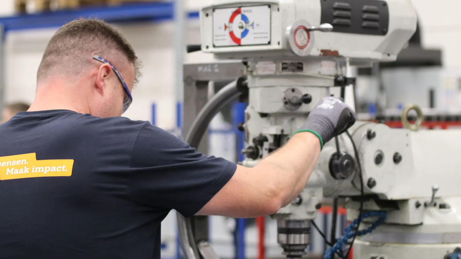
A vertical mill is a common choice for profile milling, drilling, and deep pocketing. The spindle points downward, so the tool reaches into the part from above. This setup works well when the part sits flat on the table and the cutting tools do not need to reach around the part.
Deep pockets are a strong advantage. When the tool is shorter than the pocket depth, the machine can use a longer, stiffer tool without overhang. This reduces breakage and improves finish. Materials such as steel, aluminum, and titanium respond predictably to this setup. For example, machining a deep cavity in a brake rotor or a hydraulic housing is standard vertical work. The downward force helps hold the workpiece down against the table, reducing the need for complex clamping.
Chip evacuation is another benefit. Gravity pulls chips out of the pocket. This is useful when machining narrow slots or deep cavities where air or flood coolant may struggle to clear debris. In deep pockets, chips can pack and cause tool rubbing. Gravity and a well-designed coolant nozzle directed from above help flush the debris away.
The main constraint is tool reach. Long tools for deep slots or large diameter work can introduce overhang. Excessive overhang lowers rigidity and increases vibration. If your parts require machining from multiple sides, a vertical mill may require multiple setups or a trunnion or tilt head. A trunnion allows the table to tilt, but it adds mechanical complexity and can reduce repeatability compared to a horizontal layout.
Vertical mills also handle drilling and tapping effectively. The vertical alignment provides direct access to the work surface. This is ideal for hole-making operations where precision location is critical.
How Horizontal Mills Handle Work
A horizontal mill aligns the spindle parallel to the table. The tool reaches the part from the side. This layout is useful when parts have several faces that need to be machined without frequent reorientation.
Tool length is a major factor. Because the tool enters the part from the side, shorter tools can reach the work. Shorter tools resist deflection and produce cleaner cuts. This is helpful for large parts, deep slots, and heavy machining loads. For instance, machining the side wall of a large die or a mold block often requires horizontal access because the depth of the work exceeds the safe reach of a vertical tool.
Multi-sided machining is easier. A part can be clamped once and machined from multiple faces as the table tilts or the part rotates. This reduces setup time and improves positional accuracy. A horizontal mill can often machine the top, bottom, and sides of a block in a single clamping cycle. This is particularly valuable for complex castings or forgings where precision between faces is critical.
Chip removal requires attention. Chips fall toward the floor or into collection trays. You need a good chip management system, including conveyors or vacuum systems. Poor chip control causes tool contact, scrap, and downtime. In a horizontal layout, chips can accumulate around the spindle and table, potentially causing collisions with moving components.
The workholding area is often larger. Horizontal mills can hold large castings or plates that would not fit comfortably on a vertical table. This makes them suitable for heavy-duty industrial work, such as machining turbine housings or structural components.
Comparison of Key Criteria
The table below outlines the main differences between the two layouts. Each criterion matters when you are selecting a machine for a specific production line.
| Criterion | What to look for | Why it matters |
|---|---|---|
| Part geometry | Deep pockets vs multi-sided surfaces | Vertical mills suit deep pockets, horizontal mills suit multi-sided work |
| Tool length | Short tools vs long tools | Shorter tools reduce overhang and improve rigidity |
| Chip evacuation | Gravity vs side ejection | Chips must clear the cut to prevent tool damage |
| Workholding | Flat clamping vs multi-face clamping | Fewer setups improve throughput and accuracy |
| Shop floor space | Ceiling height vs floor space | Vertical mills need room above, horizontal mills need floor clearance |
| Automation | Loading from above vs side loading | Matching automation to the layout affects cycle time |
How to Match the Layout to Your Parts
Start with the parts that make up your production volume. List the top ten to twenty part families. For each, note the dominant operations: drilling, profiling, pocketing, facing, or multi-sided milling. Mark which layout handles those operations with fewer setups and shorter tools.
Consider the material. Steel, cast iron, and titanium demand high rigidity. Vertical mills provide strong downward cutting forces. Horizontal mills provide strong side forces. Both can handle heavy loads, but the tooling and workholding differ. For example, a vertical mill is well-suited for drilling and tapping because the downward force helps seat the drill bit. A horizontal mill is better for roughing large flats because the tool can be positioned to avoid deflection.
Review your current workholding. If your parts are clamped from above, a vertical mill may integrate with existing fixtures. If parts sit on a pallet with multiple clamps, a horizontal mill may fit the process better. Check the clamping force requirements. Vertical clamping is standard for flat parts. Horizontal clamping may require custom fixtures to hold the part against the table while the tool cuts from the side.
Look at the shop floor. Measure ceiling height and floor space. A vertical mill needs clearance for the spindle and tool changer. A horizontal mill needs room for the table, chip conveyor, and operators. Ensure there is enough space for safe operator access and maintenance.
Tooling and Setup Considerations
Tooling changes with the layout. Vertical mills often use shorter, stiffer tools for deep work. Horizontal mills may use fewer long tools because the geometry reduces overhang.
Tool change speed is affected by the layout. Vertical mills use a carousel or pallet changer above the table. Horizontal mills place the changer to the side. The cycle time difference is often small, but it adds up over thousands of cycles. For example, a vertical mill with a 40-slot carousel can change tools quickly, but the changer must be positioned to avoid interfering with tall parts.
Setup time is a bigger factor. If a part needs machining from three or four faces, a horizontal mill can often do it in one setup. A vertical mill may require flipping or rotating the part. Each flip adds time and introduces the risk of positional error. For high-volume production, minimizing setups is key to maintaining cycle time.
Automation and Production Flow
Automation is a common next step after the machine is running. The layout must match the automation method. A vertical mill often loads from the top, using a robot or gantry. A horizontal mill loads from the side, often using a robotic arm or pallet changer.
Consider the part size and weight. A robot that handles small brackets may not reach a large casting on a horizontal mill. A gantry system above a vertical mill may not fit a tall spindle. Plan the automation path early. It is easier to design the layout around the automation than to retrofit it later.
Match the automation to the production line. If the next machine is a lathe or a second mill, the handoff may be easier with one layout. If parts go to inspection first, the layout may need to allow quick access to the finished face. For example, if a part requires CMM inspection, ensure the machine layout allows the part to be removed without disturbing the clamps or fixtures.
Decision Checklist
Before choosing a layout, run through this checklist.
- List the top ten part families and their dominant operations.
- Identify which parts need deep pockets and which need multi-sided machining.
- Measure the part size, weight, and required tool length.
- Review the shop floor space, including ceiling height and floor clearance.
- Check the existing workholding and fixtures.
- Plan the automation method and confirm it fits the layout.
- Evaluate chip evacuation for the chosen layout.
- Run a simulation or trial setup if possible.
- Confirm the tooling and coolant system support the layout.
- Review the maintenance access and service requirements.
Frequently asked questions
Can a vertical mill handle large parts?
Yes, but the work area and table size limit the part size. Large castings may fit better on a horizontal mill with a larger table.
Are horizontal mills only for heavy parts?
No. They are useful for multi-sided work and large tools, but they also handle smaller parts when the geometry suits them.
Which layout is easier to automate?
Both can be automated, but the method differs. Vertical mills often use top loading, while horizontal mills use side loading.
Does the layout affect part accuracy?
Yes. The layout changes how the part is clamped and how the tool reaches the work. Fewer setups and shorter tools usually improve accuracy.
Can I run both vertical and horizontal operations on one machine?
Some machines have tilting tables or trunnions that allow limited multi-axis work, but they are not a full substitute for a dedicated horizontal mill.