12-Point Pre-Use CNC Tolerance Verification Checklist
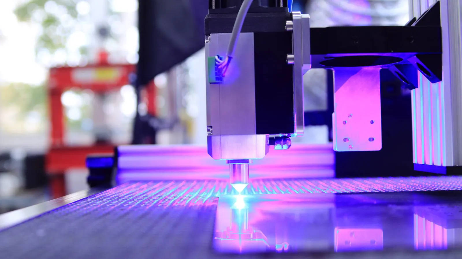
This guide provides a 12-point pre-use checklist for validating CNC machine accuracy and machine tolerance. It helps operators and engineers confirm that tolerance limits are within specification before releasing a work order to production.
- Verify machine accuracy by checking linear position, spindle runout, and thermal stability before production.
- Document baseline readings to create a traceable record of machine capability for each job.
- Red flags include inconsistent readings, tool deflection, and drift after a warm-up cycle.
- Calibrate sensors and reference points to prevent false pass or fail results.
- A structured checklist reduces the risk of scrap parts and costly rework.
Why Verify Machine Accuracy Before Production
A work order can look perfect on paper, but the machine might not be ready to hold it. CNC accuracy depends on many moving parts working in concert: the spindle, the linear axes, the control system, and the tooling. If any of these elements drift out of alignment, the part will not match the drawing.
The goal of this checklist is simple. Before the first cut, confirm that the machine can hold the required machine tolerance. This is not a theoretical exercise. It is a practical gate that separates a capable machine from a compromised one.
This procedure is not a replacement for a full metrology report. It is a front-line check that operators and engineers can perform quickly. It catches the issues that cause most scrap parts before the first tool touches the material.
1. Check the Machine State and Environment
Before any measurement, ensure the machine is in a stable state. A cold machine behaves differently from a warm one. The thermal expansion of the frame, the spindle, and the tooling changes the geometry.
Allow the machine to run at operating speed for a defined warm-up period. The control system should show stable temperature readings. The shop floor should be free from strong drafts, direct sunlight, or vibration from nearby presses or forklifts.
If the environment is unstable, the readings will not be reliable. Fix the environment first. Then proceed to the measurements.
2. Verify Reference Points and Zero Offsets
The machine’s coordinate system is only as good as its reference points. Before measuring, confirm that all tool offsets and workpiece offsets are correct. A zero offset error of even a few microns can shift the entire part.
Check the tool length offsets using a test bar. Confirm that the tool number in the program matches the physical tool in the holder. If the machine uses automatic tool changing, verify that the tool map is current.
A common mistake is assuming the previous job’s offsets are still valid. They are not. Every setup requires a fresh verification.
3. Measure Linear Position Accuracy
Linear position accuracy measures how well the axes move to the commanded position. This is the core of CNC accuracy. Use a calibrated gauge block, a ball bar, or a laser interferometer, depending on the required precision.
Run a test program that moves each axis to a known distance. Compare the actual position to the commanded position. Repeat the cycle in both directions. The difference is the error.
Red flags include errors that increase with distance, or errors that are different in the positive and negative direction. This suggests a backlash issue or a mechanical problem in the drive system.
4. Check Spindle Runout and Taper Accuracy
The spindle holds the tool. If the spindle runs out of true, the tool tip traces a circle instead of a point. This causes vibration, poor surface finish, and incorrect dimensions.
Use a dial indicator or a runout probe to measure the spindle nose. Check the runout at the tool holder and at the tool tip. The tolerance for this measurement is typically very tight, often in the microns.
If the runout is high, the tool will wear quickly. It may also cause chatter, which creates a rough surface and shifts the cutting position.
5. Inspect Tooling and Cutting Conditions
Even a perfect machine will produce a bad part if the tooling is wrong. Check the tool for wear, chipping, or coating damage. A worn tool has a different geometry, which changes the chip load and the force on the machine.
Verify that the tool is clamped securely. A loose tool can vibrate, leading to deflection. In high-speed operations, tool deflection can be significant. It changes the actual cutting position from the programmed position.
The cutting fluid should be clean and at the correct pressure. Clogged nozzles can cool the tool unevenly, causing thermal distortion.
6. Validate the Control System and Servo Performance
The control system interprets the G-code and sends signals to the servo drives. If the servo parameters are incorrect, the axes may not move smoothly. This causes positioning errors.
Check the servo alarms and error logs. Look for any history of following errors. These errors indicate that the drive is struggling to keep up with the command.
Run a jog test on each axis. The motion should be smooth and consistent. Jerky or hesitant motion is a red flag. It suggests a mechanical binding or a control issue.
7. Perform a Test Cut on a Reference Part
The final verification is a test cut. Use a sacrificial piece of material that matches the production part in hardness and thickness. Run the same program used for production.
Measure the resulting part with a CMM, a micrometer, or a bore gauge, depending on the features. Compare the measured dimensions to the drawing.
This step catches errors that the other checks might miss. It simulates the real cutting process, including chip load, vibration, and thermal effects. If the test part is out of tolerance, do not run production.
8. Document the Results and Set Tolerance Limits
Record all readings in a log. Include the date, time, operator, and machine ID. Note the environmental conditions and the tools used for measurement.
Define the tolerance limits for the specific job. These limits may be tighter than the machine’s general capability. For example, a machine may have a general linear accuracy of 5 microns, but the job may require 2 microns.
If the machine does not meet the job’s tolerance limits, flag it for maintenance. Do not attempt to force the part. This is the point where you stop.
9. Common Red Flags and How to Respond
| Red Flag | Likely Cause | Immediate Action |
|---|---|---|
| Inconsistent readings between cycles | Backlash, loose coupling, or worn ballscrew | Stop production. Inspect mechanical components. |
| Runout exceeds specification | Worn spindle taper, dirty tool holder, or worn bearing | Clean and inspect. Replace worn parts. |
| Drift after warm-up | Thermal expansion, unstable environment, or control issue | Allow longer warm-up. Check room temperature. |
| Tool deflection | Loosely clamped tool, wrong tool size, or high feed rate | Re-clamp tool. Adjust cutting parameters. |
| Following errors in servo logs | Servo gain issues or mechanical binding | Check drive parameters. Inspect axis movement. |
These red flags are not minor issues. They are indicators that the machine is not capable of holding the required tolerance.
10. Maintaining the Baseline Over Time
A single checklist is not enough. You need a baseline. Measure the machine regularly, even when it is not running a critical job. This creates a trend.
If the readings start to drift over time, you know the machine is degrading before it fails. This is a form of preventive maintenance. It allows you to schedule service during a planned downtime instead of an emergency stop.
Keep the calibration instruments up to date. A worn gauge block or a drifted dial indicator will give false results. The measurement system must be as accurate as the machine you are checking.
Final Thoughts
This 12-point checklist is a practical tool for validating CNC accuracy. It covers the machine, the tooling, the environment, and the control system. It is designed to be used by operators and engineers who need to make a quick decision: can this machine make this part?
The process is not complicated. It requires discipline and attention to detail. But it saves time and money. It prevents scrap, rework, and customer complaints.
Use this checklist as a standard operating procedure. Make it part of your setup process. Every time a new job goes on the floor, run the check. The machine will thank you. The parts will be right.
Frequently asked questions
How often should I run this checklist?
Run it before every new setup and at regular intervals during a production run. For high-precision jobs, run it at the start of every shift.
What is the difference between machine tolerance and tolerance limits?
Machine tolerance is the inherent capability of the machine, defined by its design and condition. Tolerance limits are the specific requirements of the part, which must be met within the machine's capability.
Can I use a standard micrometer to verify CNC accuracy?
A micrometer can check part dimensions, but it cannot measure the machine's linear accuracy or spindle runout directly. Use dedicated instruments for those checks.
What if the test part is within tolerance but the machine readings are off?
Check the measurement instruments. They may be out of calibration. Verify the reference points and offsets. It is possible the machine is compensating for a drift.
Does the material type affect the checklist?
Yes. Different materials require different cutting parameters and tooling. A soft material may mask a machine issue that a hard material would reveal. Always test with the actual production material.